In most cases the Profile Portable Energy Recorder will be used to monitor energy use on three phase or single phase, low voltage circuits. However, high voltage energy monitoring surveys are also possible with the Profile using the Two Wattmeter Method.
The guide below details how this can be done. Please note that this method is only possible with the Profile V monitor. The Profile IV can not be used to monitor high voltage circuits without manual alteration of survey data.
If you have a Profile IV Energy recorder and wish to perform high voltage energy monitoring surveys please contact NewFound Energy about upgrading your Profile.
What follows is intended as a brief guide only. Please see the Profile Installation Guide and the full Profile User Guide for more details as well as general installation and safety guidance.
It is assumed that the user is familiar with the basic operation of the Profile and that the Profile is set to automatic Current & Voltage ranging as will commonly be the case.
Throughout this guide where reference is made to cable phase colours, the new cable colouring is stated first with the old colour after it in italics.
Warning: Installing a Profile Portable Energy Recorder system can involve working near to exposed electricity carrying cables or bus bars and should therefore only be performed by a suitable person with the relevant electrical safety qualifications.
1. When first powered, the Profile’s LCD will show the mode of operation of the Profile e.g. ‘30 mins autologg‘, and the current date & time.
2. To instigate recording press the return key; ![]()
The display will show ‘Settling down please wait‘. If this message does not appear, remove & return power to the Profile before re-trying.
3. With a supply of 110 Volts, the Profile V will ask if it is connected to a HV circuit.
Select ‘Yes’ by pressing the up arrow ↑.
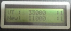
4. The VT primary voltage must then be set.
The current setting is stated in the ‘VT:…’ row.
Use the up arrow [↑] and down arrow [↓ ] buttons to change the ‘New:…’ setting. Available options are 33000, 11000 & 6600 volts.
To confirm the new selection press the enter button: ⏎
5. Once the VT primary is set & confirmed (‘VT: …’ & ‘New: …’ will match), press the escape key: ![]()
a) If the current being measured is above 6 Amps, Profile will ask you to Phase by Hand (Autophasing is not possible with high voltage surveys).
Press the escape key again:![]()
and continue to phase by hand.
b) If the current being measured is below 6 Amps, Profile will ask if the Rogowski coils are measuring a CT secondary.
6. a) If the Profile is not measuring CT secondary currents; press the down arrow button ↓ to answer ‘No’.
You will then be asked to phase by hand.
Press the escape key: ![]()
and continue to phase by hand.
6. b) If the Profile is measuring CT secondary currents; press the up arrow ↑ button to answer ‘Yes’.
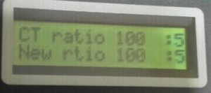
Then use the up arrow ↑ and down arrow ↓ buttons to set the CT primary.
Once set, press the enter button to confirm the new setting
7. Once the CT ratio is set and confirmed (The displayed ‘CT ratio…’ should match the displayed ‘New rtio…’.), press the escape key: ![]()
You will be asked to phase by hand.
Press the escape key again: ![]()
and continue to phase by hand.
Once successfully installed, the Profile system will record the energy use on the high voltage circuit to which it is connected.
When the survey is complete, data may be downloaded to a PC using the ProPower 3 software as detailed in the software documentation or by use of the Profile Energy Monitor App for Android.
For permanent monitoring of energy use on high voltage circuits, high voltage electricity meters are available which can be connected to our AtlasEMS Energy Management System.
For more information on this, or any of our energy management, monitoring & control systems please contact NewFound Energy Ltd.


