Case Study – Electrical Load Control Using a PLC
Create an electrical demand and load control system to suit your exact needs using the ATLAS Demand Control System and a customised PLC.
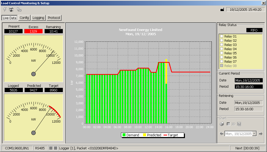
Our Atlas Demand Control System operates on a predictive basis to control a site’s period demand to a preset limit.
This can be useful where the supply transformer capacity is limited or where a capacity limit exists within the electricity supply contract for example. Under these circumstances the site total period demand (usually kVA) must not exceed the specified limit. Doing so risks heavy financial penalties or ultimately having the supply disconnected.
In situations where control of the period demand is insufficient, a PLC (Programmable Logic Controller) can be used either in conjunction with the ATLAS Demand Control Logger or by itself to add further energy control capabilities such as instantaneous present load control, average or instantaneous current (Amps) control or over-current protection for example.
A PLC can also be used as an interface between the ATLAS Demand Control Logger’s load shedding relays and the equipment to be load shed to provide an alternative output signal (e.g. 4-20mA) instead of the basic on/off of an interposing relay/contactor.
ATLAS Load / Maximum Demand Control
There are many possibilities but below are a couple of examples of how PLCs are already being used to control and limit a site’s energy use.
In this situation the period demand can be defined as the average load (in kW, or kVA) over the integration period (usually 30 or 15 minutes).
Mathematically the value is simply twice the 30 minute electrical consumption or four times the 15 minute electrical consumption.
Example 1 Steel Works in Tyne & Wear, UK
The problem:
The transformers supplying power to two furnaces have a capacity lower than the total load (kVA) rating of the furnaces;
Furnace 1 rated at 7.5 MVA, Furnace 2 at 4.5 MVA. The company was required by their electricity supplier to limit the power drawn by the furnaces to 8.5 MVA total.
Equipment in Use:
ATLAS Demand Control System.
PLC with two 4-20mA outputs.
Pulse signal from Site incoming (billing) electricity meters.
AtlasEVO Energy Management System.
The ATLAS Demand Control Logger receives consumption pulse signals from the site electricity meters. Each pulse represents 10 kVAh consumed.
The ATLAS logger records the consumption information into 30 minute integration periods and using the rate of pulses being received and consumption so far in each period, calculates an ongoing prediction of the Period Demand (KVA).
If the predicted period demand rises above the preset limit of 8500 kVA, the ATLAS logger begins to activate the 8 load shedding relays according to preset load shedding parameters.
The load shedding relays are connected to the PLC which monitors their status and adjusts its 4-20mA output signals as follows;
The furnace control system accepts the 4-20mA signal and limits the maximum furnace load as required. Via a simple key switch, control can be switched between furnace 1 & 2 as per production requirements.
Simultaneously, the PLC also receives the kVAh consumption signals directly from the site electricity meters. It uses the rate of pulses received to calculate the load (kVA) being drawn and if this rises above another preset target, the full load reduction (4000 kVA) is instigated immediately by dropping the 4-20mA outputs to 11.47mA.
An AtlasEVO Energy Management System is also used on site, communicating with the ATLAS Load Control logger, to provide energy use reports and bill checking.
Example 2 Theatre located in Kent, UK
The Problem:
The installation of a new air conditioning system and hosting of larger productions meant it was likely that the site load would exceed the capacity of installed fuses and breach the site supply capacity.
Equipment in Use:
ATLAS Demand Control System.
PLC with eight relay outputs.
Pulse signal from Site incoming (billing) electricity meter.
Three-phase Modbus meter installed on incoming supply.
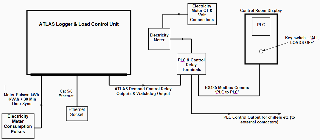
As in example 1, the ATLAS Demand Control Logger receives kVAh consumption pulse signals from the site electricity meter and calculates an ongoing prediction of the 30 minute Period Demand (KVA).
If the period demand is predicted to rise above the target of 275kVA, the eight load shedding relays are activated according to preset load control/shedding parameters. In this case the eight load shedding relays from the ATLAS Demand Control Logger are connected via suitable contactors to the air conditioning control system and air handling units in certain non-essential areas. As necessary, the air conditioning &/or air handling units in these areas are switched off to reduce the overall site load.
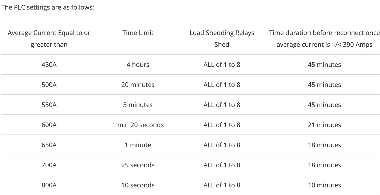
The PLC in the system operates entirely independently of the ATLAS Demand Control system to limit heat build up within the fuses on the site’s incoming electrical supply. In consultation with the fuse manufacturers, calculations were made to determine the length of time that the fuses could cope with currents higher than their specified 400 Amps rating.
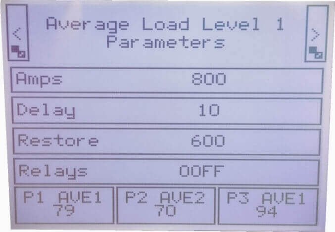
The PLC receives phase current information from an adjacent electricity meter via a ModBus RS485 link and is programmed to calculate the average current over specified time periods. If that average exceeds preset limits for a specified duration, all load shedding relays are activated, switching off air conditioning & air handling units in non-essential areas.
Load Control Relay Status Screen: shows 7 of 8 control relays activated and displays live phase currents.
Only when the load drops below 390 Amps for the duration listed does the system allow the shed loads to be reinstated. Loads are reconnected with a 1 minute delay in between each reconnection.
A Control Room Display PLC provides a user interface from where the user can check system status and adjust settings as necessary.
These are only a couple of examples of how a PLC can be used either on its own or in conjunction with an existing system to limit the electrical current, load, or total energy use on a site.
For more information on any of our energy management, monitoring & control systems or if you have a specific requirement that you think could suit a custom PLC based system, please contact us.


