The Profile Portable Energy Recorder allows electrical energy use surveys to be performed anywhere on site where supply cables are accessible. Single phase or 3 phase circuits can be monitored for a survey period of up to 12 weeks.
As detailed below, installing the Profile for a survey is a very simple process with no live voltage connection required.
When installing the Profile please follow the instructions below or the installation instructions provided at time of purchase.
Always read the installation notes in the full Profile User Manual supplied with the system paying particular attention to all electrical safety statements.
N.B. Installing a Profile system can involve working near to exposed electricity carrying cables or bus bars and should therefore only be performed by a suitable person with the relevant electrical safety qualifications.
To install and operate the system there will need to be a 13 amp socket fed from the same transformer as the load to be monitored. As an alternative to a 13 Amp socket and the standard mains lead, the optional fused probe mains kit can be used by a competent electrician to provide the voltage source for the system.
The installer should ensure that the polarity of the live and neutral supply to the Profile is correct.
Please note that this page does not detail the use of the ProPower 3 software to configure the Profile and to download & analyse survey data. For this please refer to the software help guide.
Profile Portable Energy Monitor Installation Guidance
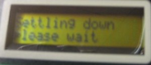
N.B. In order for the Profile to successfully complete its ‘Autophase‘ routine and for the purposes of confirming correct installation (steps 8 & 9), there must be some load on the circuit being monitored. A few Amps is usually sufficient.
A PDF version of this Profile Installation Guide may be downloaded for offline use.
1. Power the Profile using the mains lead provided. The display will show the mode of operation of the Profile e.g. ‘30 mins autologg‘, and the current date & time.
Warning: Never connect the Profile to voltages above 240 volts nominal, 268 volts RMS maximum. Connection to higher voltages such as 415 volts will cause destructive protection to operate and may destroy the instrument completely.
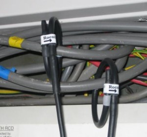
2. Connect the Rogowski coils to the Profile (via the 6-pin circular connector located on the top end of the Profile).
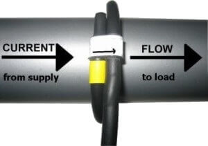
Then loop each coil around the relevant phase cable ensuring the current flow arrow indicates the direction of the flow to the load.
If the Profile system has lollipop flexible coils ensure that the label on the side of each coil faces the load.
Warning: The Rogowski Current coils are fully insulated but should not be used on live conductors (e.g. bus bars). The application of these coils is the users responsibility at all times.
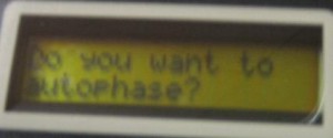
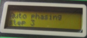
4. The Profile display will then ask ‘Do you want to autophase?’‘.
Unless you have a specific reason not to, answer yes by using the ‘up arrow’ button ↑
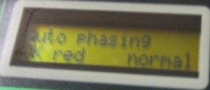
For example, the Profile might display ‘OK red normal‘. This indicates that the voltage being measured through the 13 Amp socket is phase 1 [red/brown phase] and that phase rotation is normal, ie. phase 1, phase 2, phase 3.
If phase rotation is shown as ‘reversed‘ (i.e. phase 1, phase 3, phase 2) it does not necessarily indicate a problem and recording can continue with the standard check on positive values being performed as described in steps 8 & 9 below.
7. If it is not possible for the system to autophase (usually due to very low current or poor power factor) ‘Autophase not possible‘ will be displayed and you will be instructed to phase by hand. Please see separate guide provided to ‘phase by hand‘.
8. To view the measurements being made press the Escape key ![]()
The display will revert to presenting the date/time display.
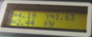
Using the up arrow ↑ and down arrow ↓ keys, different display pages may now be accessed.
9. A correct installation will usually show positive kW for all 3 phases and positive kVAr for all three phases.
If negative values are shown it is probable that one or more of the coils are either the wrong way around or on the wrong phases. Colour coded cables are sometimes incorrectly marked.
After correcting the coil installation, repeat the autophasing procedure from step 3.
Once successfully installed, the Profile system will record data relating to all three connected phases as well as the voltage reference.
When the survey is complete, data may be downloaded to a PC using the ProPower 3 software as detailed in the software documentation.
If required the Profile can also be used as a simple meter by reading the kWh & kVArh registers at the start and end of a survey to provide total circuit consumption for the survey period.
This document is intended as a guide only. NewFound Energy cannot be held responsible for incorrect data recordings caused by incorrect Profile installation.
Any customer requiring further guidance in the use of Profile should contact their supplier.


